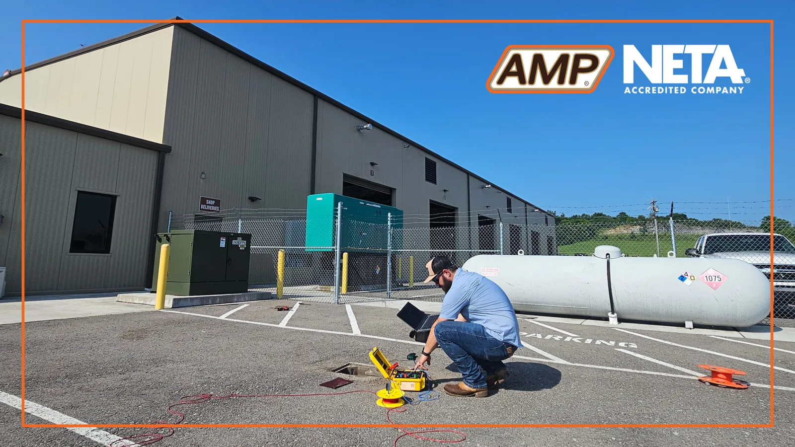
Ask anyone who's done ground testing in the field and they'll tell you: getting a number out of a test set is easy. Getting a number you can trust is the hard part.
With the Fall-of-Potential method, a reading is only as good as where you put the probes. Two things decide whether that number holds up: leads long enough to reach the plateau, and a plot that proves the potential probe actually landed on it. Let's walk through both, plus what to do when the site just doesn't give you enough room.
A quick refresher: how Fall-of-Potential works
The test uses three rods. Rod 1 is the electrode under test. Rod 2 is the current probe (C), driven out at some distance D. Rod 3 is the potential probe (P), placed between them, typically at 62% of D. The test set pushes current through the earth, measures the voltage, and calculates resistance as R = E / I.
Simple enough. The catch is that the 62% rule only works if the current probe is far enough out for the readings to settle onto a flat "plateau." Get that wrong and the number on the display doesn't mean much.
Leads that reach
Here's something that trips a lot of people up: most test sets ship with leads that are only long enough for a single ground electrode. Longer cable sets are usually sold as optional extras.
The good news? There's nothing exotic about ground-test leads. They're fourteen-gauge braided copper with rubber insulation, and any suitable wire will do the job. Most sets terminate in spade lugs, banana plugs, or bare conductors, with an alligator clip at the probe end, so you can make leads of whatever length you need from readily available materials.
Keep reading
Enter your email to read the rest of this article. One signup unlocks every article on the site.
Proving the reading
The only way to know your probe distance is sufficient is to plot distance against resistance. At a minimum, take three readings:
- The reading at 62% of the current-probe distance
- One reading a little farther out
- One reading a little closer in
If the 62% reading falls on the plateau (where moving the probe ±10% of the distance produces only a minimal change in the reading), you're in good shape. If the plot never flattens out, your current probe is too close.
How far is far enough? Take a 100 ft × 100 ft substation grid. Its diagonal is roughly 141 ft, and ten times that dimension puts the current probe about 1,410 ft out.
That's a lot of real estate, and plenty of sites simply don't have it. When that happens, it's time to switch to the slope method.
When space runs out: the slope method
The slope method is a modified Fall-of-Potential test based on the rate of change of slope. It gets you an accurate reading without stretching leads a quarter mile across the yard. Here's how it works:
- Pick a current-probe distance. Aim for at least twice the grid diagonal, or as far as the site allows.
- Take three readings with the potential probe at 20%, 40%, and 60% of that distance.
- Calculate the slope coefficient: µ = (R60 − R40) ÷ (R40 − R20)
- Look up the matching PT/C value in the table below. That percentage is where the potential probe belongs for the most accurate reading.
One important check: if µ falls off the chart, the current probe isn't far enough out.
µ lookup table
Values per IEEE Std 81. PT/C is the potential-probe position as a fraction of the current-probe distance.
- µ 0.40 → PT/C 0.643
- µ 0.50 → PT/C 0.618
- µ 0.60 → PT/C 0.593
- µ 0.70 → PT/C 0.567
- µ 0.80 → PT/C 0.540
- µ 0.90 → PT/C 0.511
- µ 1.00 → PT/C 0.480
- µ 1.10 → PT/C 0.446
- µ 1.20 → PT/C 0.408
- µ 1.30 → PT/C 0.365
- µ 1.40 → PT/C 0.317
- µ 1.50 → PT/C 0.264
- µ 1.60 → PT/C 0.204
What about clamp-on testers?
Clamp-on sets are popular for good reason. They induce a voltage on the ground under test, measure the resulting current, and calculate R = E / I. There are no probes to drive and no long leads to extend. But there's a trade-off: they have no built-in proving method, so the results are taken on faith. With a Fall-of-Potential test, you can confirm the result by changing probe spacing.
Here's how the two stack up:
Fall-of-Potential
- Setup: Three probes driven at measured spacings
- IEEE 81: Conforms to ANSI/IEEE Std 81
- Requirements: Space for the current probe and long leads
- Verification: Confirmed by changing probe spacing
- Best use: Commissioning, substations, and reference readings
Clamp-on
- Setup: Clamp around the conductor; no probes
- IEEE 81: Does not conform to IEEE Std 81
- Requirements: A good, low-impedance return path
- Verification: No built-in proving method
- Best use: Fast checks on multi-grounded systems
The bottom line
A ground resistance number is only useful if you can stand behind it. Bring leads that reach, plot at least three points to prove you're on the plateau, and when the site runs out of room, use the slope method instead of guessing. Clamp-on testers have their place for quick checks, but when the reading really matters, Fall-of-Potential is the one you can prove.
- ANSI/IEEE Std 81: Guide for Measuring Earth Resistivity, Ground Impedance, and Earth Surface Potentials of a Ground System.
- IEEE Std 81.2: Guide for Measurement of Impedance and Safety Characteristics of Large, Extended or Interconnected Grounding Systems.
- Jowett, Jeff. "Measuring Ground Resistance – Fall of Potential Method." NETA World, Spring 2002.
- Jowett, Jeff. "Slope Method." NETA World, Summer 2002.
- Getting Down to Earth, Megger, 2005.